E30 AND E28 CAMBER AND TOE CORRECTION KIT INSTALLATION GUIDE - K0006-EH-K0541-K0471


Disclaimer
Technical Information/Advice Use-At-Your-Own-Risk-Disclaimer: We offer all email, telephone, and posted technical information / advice on our site TO BE USED AT YOUR OWN RISK. We offer no guarantee that your interpretation or skill in implementing the information we provide will achieve your desired result. Use common and be safe. We are not responsible for injuries or damages.
The symptoms
These brackets are a must to be able to align the rear of your classic BMW. That's especially true if you have lowered your car. When you lower your classic BMW like E30, E28, or even 2002, the rear camber shifts towards negative degree measurements which causes an uneven contact patch. This results in shortened tire-tread life and possibly worse handling qualities depending on the severity.
Applicable for products -
- Eccentric Complete Garagistic Toe and Camber Correction Kit
- Shim Complete Garagistic Toe and Camber Correction Kit
- Serrated Complete Garagistic Toe and Camber Correction Kit
Tools
- Electric dremel or die grinder
- Carbide endmills
- Electronic Level (Harbor Freight)
- Welder (MIG or TIG)
- Metal Files
- Clamps
- Common sense and safety equipment
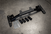
Each Garagistic "complete kit" includes 8 brackets. This is enough to do BOTH camber or toe. If you order a half kit, you can either use it do adjust either camber OR toe. You need to order the complete kit to make the rear subframe fully adjustable for both camber AND toe. The subframe has 8 mounts (2 mounts on outside and 2 mounts on each wheel).
To correct camber the brackets go on the inner mounts (closest to diff), and toe would go to the outer mounts (closest to the wheels). The camber brackets (inner tabs) should be welded with the slots going up and down. The toe bracket (outer tabs) slots should be horizontal.


Set initial ride height and if possible get your current alignment specs
To make sure you get the amount of correction you need we always recommend that you set your final ride height first. It is then best to go to an alignment shop and see where the camber and toe values stand the way they are. This will tell you where the brackets should go. We know that it is not always easy to go to an alignment shop for values first, but this is the ideal way to do it. These instructions and pictures will show the placement that will benefit most lowered e30s.
Camber/Toe Bracket Leveling
Make sure that you are putting the brackets straight. For this, we recommend you to remove your subframe bushings (which we recommend replacing anyways while your subframe is removed) and using a 2x4 piece of wood on the top and bottom of the subframe mounting point and clamping it down to the table on both sides.
Make sure your work space is level before you start, this will help make sure everything is 100% straight. There is a ±0.5° of tolerance. The top of the differential mounting point is an excellent place to check this but be sure to check the level perpendicular to the subframe as shown in the photo below. Zero your level to this measurement

Once the level has been zeroed, you can then mock up the camber/toe brackets in the appropriate mounting points and level it using the level against a straight edge that levels both sides of the bracket as shown in the photos below. Slightly tighten the brackets in place using our factory hardware in order to get the brackets to stay while leveled before you move on to the next step.


This is where the optional shim kit would be used in order to keep the brackets straight. Be sure to orient the bracket with the openings as shown below in order to get the most effective adjustment range. If you are looking to get a more extreme adjustment with extra + or - camber, refer to the photo below and mount your bracket accordingly.

Once the plates are located in the place you want them, tack them in place. A clamp will help quite a bit here, although you could also use your eccentric hardware to hold them in place. If you are MIG welding, make sure to use anti-splatter so nothing gets on the adjustment plane. Once tacked, remove the bolt and complete the weld. We prefer TIG welding in this process. Less mess and more precise. Remember to prep the area prior to welding.

We prefer to weld brackets in place before slotting. This makes it much easier in our opinion but the photo below shows an alternative method for the camber bracket which shows the cutting of the tab before tacking the bracket.

Slotting the Mounting Points
This is where a die grinder and and carbide endmill will save you a lot of time. Using all proper safety equipment, you can start to slot the holes. Use the brackets as a template, but try not to touch the bracket with the endmill. Patience here is key! After you're done, file down all sharp edges. Use care here.

NOTE - Photos show Eccentric/Shim kit brackets installed but same principle applies to the serrated brackets as well.
Toe Correction Instructions
The toe brackets are installed in almost the same fashion as the camber kit. The major difference is that the bracket get centered to the existing mounting hole as pictured below.

Toe brackets are added to the outer trailing arm pickup points (closest to the wheels/subframe bushing mounting point) and must be oriented horizontally (not up and down!). Centering the hole with the slot in the bracket will get .625 degrees of toe correction in either direction. Again, this would be the time to take a look at your initial toe alignment spec sheet and adjust as needed.
The procedure here is the same as the camber brackets, once brackets are in a place you want them (and are level), tack them in place. A clamp will help quite a bit here, although you could also use your eccentric hardware to hold them in place. If you are MIG welding, make sure to use anti-splatter so nothing gets on the adjustment plane. Once tacked, remove the bolt and complete the weld. We prefer TIG welding in this process. Less mess and more precise.
We prefer to weld brackets in place before slotting. This makes it much easier in our opinion.

Its a good idea while your here to reinforce the mounting points on the diff mounts using our kit. They are found here:
E30 Differential Mounting Point Reinforcement Kit
Be sure that the metal is cleaned and prepped before welding. Below is an example of a powder-coated subframe.


