Assuming you meet the following conditions:
You have an ‘88 - ‘91 E30 motronic 1.1, 1.2, or 1.3
You have an E32/E34 engine motronic 1.1, 1.2, or 1.3
You have 2 options here…
1. If your E32 came from an automatic transmission car, then you might want to consider option 2. If not, then you will have to wire and bypass the automatic transmission park. My E32 came from an automatic car. I tried fervently to wire it up, then gave up and simply went to option 2. If you must, then good luck. The E32 engine that I bought has 2 plugs. I tried to take the regular ECU from the M30 engine (ECU 0 261 200 179), and put slap it on. On the C-101 plug (by the fuse box on firewall), there is a round engine plug. Take the harness from my E32 engine and plug it directly in. That should send gauge signals and ignition stuff through. All in all, it wasn’t a direct plug-in and I couldn’t figure out which wire went where. Take a look at what it looked like trying to find the automatic park:

2. Take the E30 engine wiring harness that you had when you removed the old engine (assuming it was a manual) and lay it across the M30 after the M30 is dropped in your car. Extend some wiring to meet certain sensors (they are in different positions than in the M20/M10/M42 ). Think about it. The harness is made for your car specifically. You can use the same M30 ECU that came with the engine (automatic or manual car, doesn’t matter). All of the sensors on your M20/M10/M42 will be exactly the same on the M30, just in a different place on the engine. Same crank sensor with same number of wires, oil pressure switch, oil level sender, coolant sender, temp sensor.. carbon canister…etc. Obviously the C101 port will match up fine because IT’S FROM THE SAME CAR. All of your gauges should work perfectly with no calibration needed. Think about it as your car not knowing that a different engine was even dropped in. I do not know if a 13 button OBC will work. I hooked up an analog clock, so didn’t bother with that stuff. I had a supereta, so needed a new tachometer plug and tachometer to meet the 7k.
Example of motronic 1.3 ECU connector. Note that it has 3 rows of pins. That is common on all E34 and E32 M30 engines as well as any E30 made after 1988.

19.1.1
19.1.1.1 TOOLS REQUIRED

19.1.1.2 TIME & $$ 1Hr & $0
19.1.1.3 INSTRUCTIONS
The following instructions relate directly to “E30M30 Wiring” Attachment.
The instructions for the Electrical section are quite self-explanatory. You must basically break down the electrical efforts by answering the following questions: 1. What E30 do you have? a. Easiest: If you have an ’88-’91 E30 325i, C101 is almost a direct plug/play b. Harder: If you have an ’85-’87 E30 325e/i, the C101 is somewhat more involved and may require pin-out changes. c. Hardest: If 318, you will have more extensive wiring as found in Figure 53 . C101 is actually a rectangular connector. 19.2 C101 PIN-OUTS
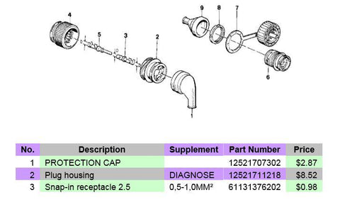
I’d like to provide more of a background of the part numbers associated with C101 in the event of needing to order more pins. Please see below:

Now, let’s talk pin-outs. Please take a look at Figure 54 Example of Pin-out Chart, which gives some examples of E30’s and M30’s. If none of these models apply to you, then you’ll at least be able to see the example highlighted below in blue and do research through the schematics on your own.
Here is what the typical pin-out chart will look like in the following pages:

The page numbers specifically refer to the page within the wiring diagram of interest. The page number is not the page number on the document itself; It is the page number of the adobe acrobat file.

Above in Figure 56 above, I have included a quick example to help read the schematics.
Please refer to the E30M30 Wiring Attachment for details on your model/year of E30/M30.
So for many E23, E24, and E28 M30’s, the Fuel Rate Output and Engine Tach output was originally through a separate connector and routed through the chassis wiring.
For the purposes of this swap (for all E30’s with Round C101 connector), you will need to take the wire from the ECU and route it through the engine wiring harness through the proper pin on the C101 connector to look and act stock.
For E30’s with the rectangular connector, will need to splice from the C103 (Pg 132 of ‘85 318i Schematic) into C101 Connector. Pins must match from the engine side to the chassis side. Similar instructions are to be found on the “notes” section below the pin-out table.
19.3 WIRING DIAGRAMS
I have included the following popular E30 and M30 model/years:

Each tab on the excel spreadsheet will have the wiring pin-out chart, the cover page of the wiring diagram of interest, the color code chart, and the C101 or X20 pin-out. C101 is found on all E30’s and the E28/E23/E24 cars. The X20 is found only on the E32 and E34 cars. It is just a naming convention.
If you still need more help, there is more information. These are simply links to the “Mitchell diagrams”. http://www.autolib.diakom.ru/CARS2/index.html. Please follow these steps to locate the files.
1. Click on BMW on the left hand column.
2. Click on the link that reads, “Принципиальные схемы.”
3. Then below, click on the text that reads, “Принципиальные схемы из Mitchell On-Demand.”
4. Then click on the drop down menu to find the year and model of your car. It gives you 10-12 figures to look at for the model of your choice. They’re all *.pdf and accurate.
It gives you something that looks like this, which is not BMW Factory, but it is 90% credible enough to obtain some high-level information about your car. See Figure 57 below.

The engine compartment files are probably the most important, but the fuse box diagrams are helpful as well just in case you need to trace a wire all the way back.
Another source is to also use the electrical troubleshooting manuals at the following link. http://wedophones.com/BMWManualsLead.htm
If you refer to Figure 58, you’ll see a nice tie-in to what I’m talking about. For my swap, I did all the research myself for the ETM’s for both my M30 wiring harness & the E30 I swapped into. In this case, I’m referring to an ’89 735i and an ’88 325iC. For reference, I added the page numbers where I found the information relative to each pin. It’s part of the “description” column in Figure 58. I added notes below and color-coded some important pins which required relocation/splicing so it could fit my application and be as stock as possible. You can read through it and decide for yourself if you want your swap to be as extensive electrically.
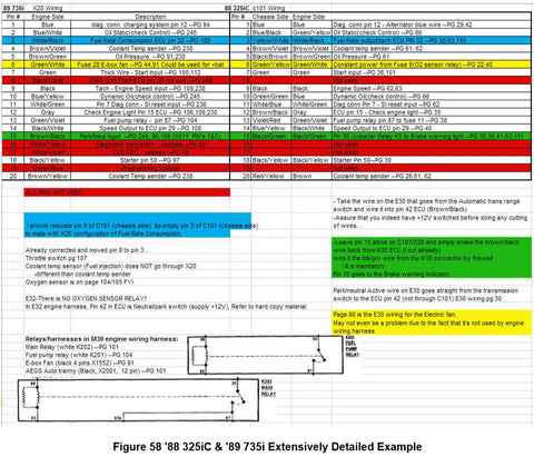
As stated above, the page numbers in the “description” column refer to the pages in the Electronic Troubleshooting Manual, which are provided. Each Manual is slightly different. If you have a swap with unconventional year M30/E30 combinations, then you might want to strictly refer to the wiring diagrams and find the location of each and every pin on the C101/X20 port. It’s quite laborious, but it is very useful and helpful for getting it right the first time. I hope and think that I have provided you with enough information that you won’t have to go through that extensive research.
19.4 BYPASSING AUTOMATIC TRANSMISSION WIRING
19.4.1
19.4.1.1 TOOLS REQUIRED
19.4.1.2 TIME & $$ .2Hrs & $2
19.4.1.3 INSTRUCTIONS
If the M30 you received came from a manual car, then skip this section. If you received an automatic wiring harness however, you must follow these steps. Both my M30 and E30 were Automatic, so I had to do these steps. There are 2 aspects to this procedure. The first being what’s done on the E30 wiring side and the other being what’s done on the M30 engine wiring harness side. Please read carefully.
Let’s do the E30 side first. Please refer to Figure 59 for the schematic that highlights the Automatic Transmission Range Switch located by the shift console in your E30, connector C306. When you remove your automatic transmission, you will disconnect C306 and need to short it according to Figure 59.

Short pins 3 and 9 on the C306 connector. If you trace this wire all the way back to the ECU pin 42, you’ll see that it is ultimately RD/BU after going through C131 connector. You can cut this before or after the C131 connector, but I cut it before and will explain that way. This wire, once cut, will now provide the constant 12V to your new M30 ECU, pin 42.
On the M30 wiring harness side, we’re going to try to do 2 things at once in retaining all of the functions and stock behavior of your E30/M30. You’ll need to start at the X20 connector. The wire of interest is the Brown/Black wire from Pin 15. This wire goes STRAIGHT to pin 42 on the ECU, but you don’t need this function anymore. You need to cut the wire about 10” before it gets to the ECU connector. On the connector side, you’ll splice this cut wire with your Green/Black wire you spliced earlier. I would make it a connector that is easily removable in case you need to remove the wiring harness for any reason.
Now you have adequately and elegantly provided 12V to the ECU pin 42.
But now you have that Brown/Black wire hanging out in the wiring harness. We can use this for something useful. If you look at your E30 wiring diagram, (here, in Figure 60), you’ll see that pin 15 on the C101 port originally went to the starter. You need to take this rouge Brown/Black wire and mount it on the starter as it was originally designed that way for the E30.

Also referring to Figure 58, the automatic wiring is partly highlighted in Green and discusses Pin 15.