This electrical summary will discuss only the M60 wiring. This will not cover OBDII wiring in the M62. The reason being is that in 1996, the standards changed from the DOT and all cars were forced to implement on-board-diagnostics (OBD). Originally, it started in 1995 with OBD I, which was relatively archaic, but in 1996, they rolled out OBDII and this was to be installed on every single car sold in the US, spanning many manufacturers. As a result, the way that the ECU’s store and annunciate failures of the engine management system has been completely overhauled. What does this mean for the average BMW Engine swapper? Quite a lot:
1. No more simple C101 connection re-pinning
2. Standard Parallelogram-shaped OBDII Diagnostic port, integrated in many cases into the entire body electronics.
3. CAN was introduced at this time, which is a high-speed bus that communicates with the ECU, instrument cluster, and other computers on the BMW’s chassis.
4. EWS Anti-theft device was also added in BMW cars, which indicates that a chip inside the key induces a voltage via a small antenna ring on the ignition tumbler to properly identify itself to the ECU so that the ECU will allow the car to start.
Many of these features can be disabled via an ECU Flash, but it takes a dedicated service, such as Ergen Motorsport to implement that level of change. However, it certainly can and has been done.
This section will not discuss any of that. If you are interested in swapping an OBDII engine (Year 1997 and newer) into your E30 or other older chassis, I encourage you to purchase my M62/S62 swap write-up. This will have all of the detailed pinouts necessary to essentially create your own wiring harness and adapt it to your chassis. This incudes either flashing your ECU or pulling the entire EWS system from your donor car to adapt to the E30
Ok, now let’s talk pin-outs. Please take a look at Figure 102 which gives a couple examples of E30 ECU’s and M60’s. If none of these models apply to you as shown in Table 15, then at least you’ll at least be able to see the example highlighted below in blue and do research through the schematics on your own.
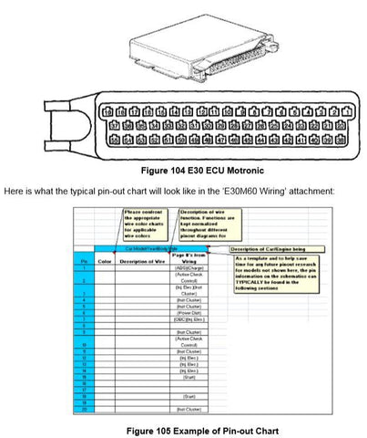
The page numbers specifically refer to the page within the wiring diagram of interest. The page number is not the page number on the document itself; It is the page number of the adobe acrobat file.

Above in Figure 107 Engine/Chassis Wiring Example I have included a quick example to help read the schematics. C101 means E30 connector and X20 means M60 body connector, but both terms have the same meaning.
20.1.1.1 TOOLS REQUIRED
- Wire Snips
20.1.1.2 TIME & MONEY
- 2.5 hours and $0
20.1.1.3 INSTRUCTIONS
The following instructions relate directly to “E30M60 Wiring” Attachment.
The instructions for the Electrical section are quite self-explanatory. You must basically break down the electrical efforts by answering the following questions:
1. What E30 do you have?
a. Easiest: If you have an ’88-’91 E30 325i, C101 is almost a direct plug/play
b. Harder: If you have an ’85-’87 E30 325e/i, the C101 is somewhat more involved and may require pin-out changes.
c. Hardest: If 318, you will have more extensive wiring, C101 is actually a rectangular connector.
20.2 C101 PIN-OUTS
I’d like to provide more of a background of the part numbers associated with C101 & X20 in the event of needing to order more pins. Please see below:


Each page will have the wiring pin-out chart, the cover page of the wiring diagram of interest, the color code chart, and the C101 or X20 pin-out. C101 is found on all E30’s. The X20 is found only on many other models (listed above). It is just a naming convention.
Before I start, I’d like to give you more of a background of the part numbers associated with C101 in the event of needing to order more pins. Please see below:
There are options for modifying the connectors. This is because of 2 reasons.
1. The X20 connector is located ON the M60 engine – Not remotely via wires. Figure 112.
2. The X20 is 25 pin and the C101 is only 20 pin – An adapter must be made at a minimum.
I will highlight both options below:
Option 1 (recommended): Entirely Remove E30 C101 – Extend the wires directly to X20
This option is preferred and is the option I decided to choose. Basically, you cut the C101 out COMPLETELY from the picture. Then you splice/solder each wire, follow the wiring pin-outs that I describe below for your model, and solder them to the X20 pigtails as shown in Figure 113.

I do not see any immediate drawbacks to performing this modification. You are already performing enough modifications to your E30. This should be non-consequential compared to the welding and cutting you’d be doing to retrofit your brakes.
Option 2: Keep E30 C101 and make an adapter cable to X20
This option is preferred if you plan to revert your E30 back to stock in the future and do not want to make any modifications to the E30 Chassis. See below.

The drawbacks I see to performing the mod this way is the amount of effort needed and the additional clutter in the engine bay that you’d now have by the addition of another connector. There is no added value to having this connector. If you must remove it, all you need to do is remove the air intake cowling and you can easily expose the X20 connector to remove it for any type of diagnosis.
Please refer to the E30M60 Wiring Attachment for details on your model/year of E30/M60.
20.3 WIRING DIAGRAMS
Please refer to the E30M60 Wiring Attachment for details on your model/year of E30/M60.
I have included the following popular E30 and M60 model/years. I am not providing S62 Wiring due to the very integrated body electronics. There is much more than X20 wiring to be concerned over.
Table 15
| E30 Model/Year |
| 1986 325e |
| 1989 325i/is |
| 1988 325iC |
| 1985 318i (early production) |
| 1985 318i (late production) |
| M60/B40 Model / Year |
| 1995 540i / E34 |
| 1993 740i / E32 |
| 1994 840i / E31 |
Each tab on the excel spreadsheet will have the wiring pin-out chart, the cover page of the wiring diagram of interest, the color code chart, and the C101 or X20 pin-out. C101 is found on all E30’s and the the X20 is found only on the E31, E32, and E34 cars. It is just a naming convention.
For the purposes of this swap (for all E30's with Round C101 connector), you will need to take the wire from the ECU and route it through the engine wiring harness through the proper pin on the C101 connector to look and act stock. For E30's with the rectangular connector, will need to splice from the C103 (Pg 132 of '85 318i Schematic) into C101 Connector. Pins must match from the engine side to the chassis side. Similar instructions are to be found on the "notes" section below the pin-outs for each model in the attachment.
If you still need more help, there is more information. These are simply links to the “Mitchell diagrams”. http://www.autolib.diakom.ru/CARS2/index.html.
Please follow these steps to locate the files.
1. Click on BMW on the left hand column.
2. Click on the link that reads, “Принципиальные схемы.”
3. Then below, click on the text that reads, “Принципиальные схемы из Mitchell On-Demand.”
4. Then click on the drop down menu to find the year and model of your car. It gives you 10-12 figures to look at for the model of your choice. They’re all *.pdf and accurate.
It gives you something that looks like this, which is not BMW Factory, but it is 90% credible enough to obtain some high-level information about your car. See Figure 115 below

The engine compartment files are probably the most important, but the fuse box diagrams are helpful as well just in case you need to trace a wire all the way back.
Another source is to also use the electrical troubleshooting manuals at the following link. http://wedophones.com/BMWManualsLead.htm
Please refer to the E30M60 Wiring Attachment for details on your model/year of E30/M60.
20.4 BYPASSING AUTOMATIC TRANSMISSION WIRING
20.4.1.1 TOOLS REQUIRED
- Various
20.4.1.2 TIME & MONEY
- .2 ours & $2
20.4.1.3 INSTRUCTIONS
If the M60 you received came from a manual car, then skip this section. If you received an automatic wiring harness however, you must follow these steps. Both my M60 and E30 were Automatic, so I had to do these steps. There are 2 aspects to this procedure. The first being what’s done on the E30 wiring side and the other being what’s done on the M60 engine wiring harness side. Please read carefully.
Let’s do the E30 side first. Please refer to Figure 116 for the schematic that highlights the Automatic Transmission Range Switch located by the shift console in your E30, connector C306. When you remove your automatic transmission, you will disconnect C306 and need to short it according to Figure 116.

20.5 ELECTRICAL EPILOGUE
Regarding the wiring pinouts for C101, X20…etc, the assigned colors for a specific engine function seems to carry through a common theme from model to model. See Table 16.
Table 16
| Function | Wire Size (mm2) | Wire Color |
| Alternator Wire | .5 (small) | Blue |
| Starter Wire | 2.5 (really thick) | Black/Yellow |
| Fuel Pump Relay | 1.5 (medium) | Green/Violet |
| Tachometer | .5 | Black |
| Oil Level (st & dyn) | .5 | Follow same themes together – Different stripe color |
| Check Engine Light | .5 | Gray |
I have a high confidence rate that even though the pin assignments changes from model to model and year to year, you will typically find that these wires, which are the general wires you need to get the car started and running, is relatively consistent across the board.
20.6 ENGINE GROUND
The engine ground wire needs to be added to the swap. The wire should be no smaller than 2 gauge wire and should connect the block of the engine (or the engine mount bracket) to the chassis. If there is paint on either, it should be scraped so there is continuity between the engine (any metal point on the engine) to the chassis (any exposed metal).
If you use a continuity tester or multi-meter, you should be able to easily test continuity from Chassis to engine. This is highly suggested.
20.7 CARBON CANISTER WIRING
20.7.1.1 TOOLS REQUIRED
- Various
20.7.1.2 TIME & MONEY
- .3 hours & $2
20.7.1.3 INSTRUCTIONS
The Carbon Canister needs to be wired. The purpose of the carbon canister is to prevent the fuel tank from getting too pressurized and/or allowing fumes to get into the engine bay. It equalizes the pressure in the fuel tank and is necessary for a well thought-out swap. See below in Figure 117 for details on how to wire the carbon canister with the existing E34 engine wire harness. It’s not a direct plug in and wires need to be extended to relocate the canister to wherever you decide to mount the actual carbon canister.
For installation suggestions, please see CARBON CANISTER section of this swap. This section exclusively covers the wiring. This wiring as shown in Figure 117 is from the aspect of the ’95 540i. Please refer to your specific car for the wire color and/or connector designations.

20.8 TACHOMETER ADJUSTMENT
20.8.1.1 TOOLS REQUIRED
- Various
20.8.1.2 TIME & MONEY
- 1.5Hrs & $90
20.8.1.3 INSTRUCTIONS
Your E30 has 4 or 6 cylinders. You are swapping an engine that has 8 cylinders. Your instrument cluster tachometer operates off of a duty cycle square wave signal that comes from your crank position (or most likely the ECU, although the signals are relatively the same). The purpose of a remote tach signal converter is so that you trick your instrument cluster into thinking that it’s reading 6 cylinders. The module changes the duty cycle of the incoming tach signal to match what the instrument cluster expects.
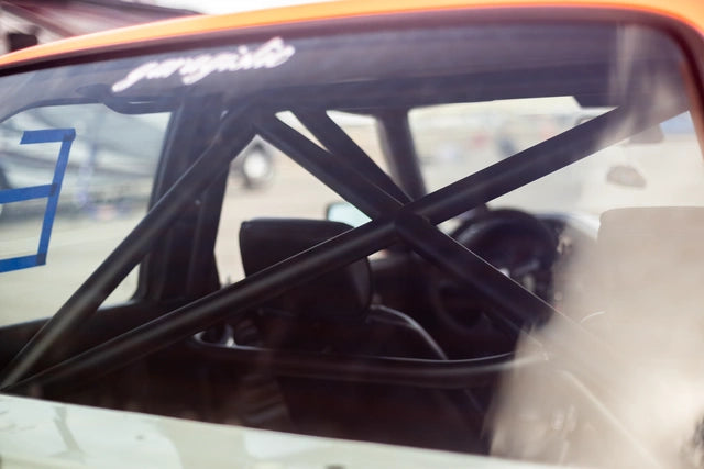
I decided to make it easy on myself and use a Garagistic tachometer adjustment. Check their site for latest pricing. Current pricing is shown in section 20.8.1.3.
It makes the swap so much easier than trying to create one yourself. Please note that you do need to obtain the 4 cylinder coding plug to make this work. Figure 118 shows the Garagistic tachometer adjustment module.

It’s small, sleek, easy to install, operate, and adjust. Installation into the E30 can be found on Figure 119. The signals can be seen below for installation
red - 12V ( on ignition)
brown - GND
white - signal input (from engine control unit) – on Figure 119, is green for illustration purposes.
yellow - output (to instrument cluster)

20.9 13 BUTTON OBC MPG ADJUSTMENT
20.9.1.1 TOOLS REQUIRED
- Various
20.9.1.2 TIME & MONEY
- 1.5Hrs & $90
20.9.1.3 INSTRUCTIONS
An adjustment needs to be made or else your OBC MPG gauge (and your instrument cluster MPG needle) will read up to 60MPG average for your trip. While this is impressive, it’s false and can get annoying.
You can buy an apparatus to adjust the MPG given the engine you swap from Seattle circuit.
http://www.seattlecircuit.com/fuel_signal.htm
According to Figure 120, this module is designed to correct for larger than stock fuel injectors on most Bosch equipped vehicles. The OBC usually displays an inflated mileage and range information. The fuel signal converter digitally conditions the fuel signal to match the signal for the stock injectors meant for the M20.

You might find that the adjustment on the unit from this supplier is simply not enough to get you down to your actual MPG. This was the case with me, even with the adjustment all the way turned. Please contact the supplier and they will get you set up as they did with me, and promptly. Great customer service. The instructions that come with this unit are very straightforward. They discuss how to measure against your actuals and adjust with the Bourns potentiometer. It’s really a very nifty unit.