This is one of the most comprehensive sections of the write-up. This is because of its importance and its relevance to the swap. There are many aspects of brakes that were considered here including (but not limited to), relocating the pedals, booster, MC, ABS, lines…etc. Please read the following section very carefully before you perform any modifications.
The minimum requirement for the pedal aspect of this write-up assumes you have the ambition and the time. Therefore, while it may take more time to make a custom pedal setup from scratch as I describe in sections 23.2, 23.4, and/or 23.3, it will give you the opportunity to stretch your technical abilities. If you decide that you would like to go to a boosterless setup then you can easily get it sourced by Garagistic. As shown below in 23.1.
23.1 BOOSTERLESS SETUP
Pedal modifications are paramount to executing an effective swap. In my opinion it was one of the most stressful and difficult, so I will attempt to cover it in as much detail as I can.
Garagistic distributes a wildwood kit that includes the brake pedal and clutch pedal. Check their site for latest pricing. The brakes are boosterless, so it saves a lot of time and effort in relocating the brake booster. Note that the feel of your brake pedal will be stiffer. This is acceptable to most drivers as you drive, you get used to it.
This is called the “booster delete”. This requires minimum fabrication and runs as a direct fitment from Garagistic. The brake booster relocation is the hardest part of the v8 into e30 swap! The factory booster is in the way. Some choose to use e32/e34 booster setup and relocate behind the headlight. This is costly, requires lots of custom work, clutters engine bay, and requires the removal or relocation of the complete abs setup including brake lines. This is described in this manual.
With this boosterless brake setup bracket, swap time is shorter, and swap is cleaner. Garagistic’s boosterless brake bracket allows you to use wilwood or tilton pedals/master cylinders. Everything is relocated tightly and neatly under the dash in the factory pedal area. When the conversion is done, its’ all hidden! Simply mount the reservoirs in your engine bay. It’s a super easy way to get a wilwood pedal box for your e30.
Mounting (body side) consists of three of the factory holes under the dash + three holes near the firewall that need to be drilled. Bracket is completely assembled and tig welded (certified welder) on arrival. All hardware is supplied.
We recommend using masters with 5/8" bore front and rear master cylinders for this swap. These are the most compact masters and the smaller bore means that effort will be bearable (especially if you plan to run these on the street).
To help educate you on the theory behind brake hydraulic systems: Bigger the bores means Minimal pedal travel/stiffer pedal/higher pedal effort. Smaller bores mean long pedal travel/softer pedal/less pedal effort. All grade 8 hardware included. Pedals/master cylinders/brake switch are not included and must be bought.
This pedal mount does not work with airbag steering columns. To use this mount in an airbag car, a non-airbag steering column must be installed first.
Additional holes need to be drilled to accommodate the new setup. This will be explained in the next section. Works on left hand drive cars only. Please refer to Figure 131 for pictures of the installed boosterless bracket setup exclusively sold by Garagistic.

23.2 BRAKE PEDAL MODIFICATION
23.2.1.1 TOOLS REQUIRED
Various – Basic Tools
23.2.1.2 TIME & $$
- 2.5Hrs & $10
23.2.1.3 INSTRUCTIONS
However, if you wish to challenge yourself technically and you do not want to spend the money on a boosterless setup, or you prefer the completely stock feel of BMW brakes, then you can read below as to how one would modify the pedal assembly manually.
You must modify your brake pedal linkage. This entails moving the pivot point on your brake pedal to the left approximately 3-4”. This does not have to be exact, but it does need to be enough to clear the M60 cylinder head. I moved it 4” so that my E34 linkage mounted in the engine bay as close to stock as possible. I recommend 4”, but if you do it less than that, be aware of the downstream risk of further modifications to your E34 linkage assembly.
You must use as thick of a material as you can when relocating the pivot point. In this case, I used 3/8” thick steel and welded it directly to the side of the existing pedal and braced it as well. Below, in Figure 132, you can see how I modified it, the distance I moved it, and how the linkage hooks up to it.
I decided to leave the previously existing linkage mounting point alone.

The firewall also needs to be modified in multiple ways. While the pedal assembly mounting points to the firewall remain unchanged, there is now a spot for the brake pedal rod to exit the firewall where there was no spot before. See Figure 133 for details of what needs to be modified. Again, I cannot tell you the distance that things need to be moved. It is dependent on your specific swap.
I moved my brake pivot point 4”, so I moved most of everything else 4”.

23.3 CLUTCH PEDAL MODIFICATION – STEEL
(PREFERRED TO SECTION 23.4)
23.3.1.1 TOOLS REQUIRED
Various – Basic Tools
23.3.1.2 TIME & $$
- 4Hrs & $25
23.3.1.3 INSTRUCTIONS
I decided to change from the plastic to steel for a number of reasons. The modifications are much easier being steel. You can weld any mild steel rod/plate to it. It feels much stronger than the plastic version and is less susceptible to torsional stress (twisting the pedal around its longitutional axis).
There are things that you should be careful about. And that is the welding. You mustn’t weld too fast or too hot as you risk warpage of the pedal and the bushing that mounts it to the main pivot bolt. When modifying the steel pedal, you want to break it up into 3 steps:
1. Move the Master cylinder mount over approximately 7/8” as shown in Figure 134. It’s the front view. Cut the old part out and weld it in to the new location.
a. When you do this, you see in Figure 134 that I had to modify the actual pedal to make room for the master cylinder boot. When you cycle the pedal action, the boot mustn’t get caught up on the pedal length itself. This is exemplified in Figure 137 and Figure 137.
2. Now it’s time to actually mount the Master Cylinder. You must move its stock mounting location app. Like you moved the master cylinder mount 7/8”, you must also move the Master Cylinder the same amount. This is to ensure that you have enough room to clear the brake linkage to its new location. I do not have any pictures of this.
a. Drill 2 holes in your steel and tap them so that you can install M8 bolts that go through the master cylinder mounting bolts.
3. The third step is to make sure that the clutch return spring is mounted properly
a. This is not a difficult step, but is somewhat time consuming. Again, make sure that you do not weld the pedal pivot joint too fast or hot or it will warp.
b. The pedal retention spring hardware is shown in Figure 138.


23.4 CLUTCH PEDAL MODIFICATION- PLASTIC
(OPTIONAL TO SECTION 23.3) 23.4.1
23.4.1.1 TOOLS REQUIRED
Various – Basic Tools
23.4.1.2 TIME & $$
- 6Hrs & $20
23.4.1.3 INSTRUCTIONS
My car was a 1989 325is. The plastic clutch Pedal came on E30’s from ‘88-‘91 and all ’92 convertibles. This was BMW’s upgraded version that was just as strong while being relatively cheap to build and light. Unfortunately for us aftermarket modders, this makes the pedal very difficult to modify for the swap. Allow me to elaborate on why this is and what needs to be modified.
Since we moved the brake pivot point over 4” to the left, we must now move the clutch master cylinder over approximately 2-3” to the left. This introduces a number of problems that is not impossible to overcome, but very difficult. Figure 139 shows the unmodified pedal assembly.

The first step to mod the pedal assembly is to make sure that your momentary switches remain in an unchanged state, so there is a 3 picture storyline that shows just that. See below in Figure 140. This will ensure that you have enough room for the new location of the brake pedal pivot rod to go.
So now you have the Brake Pedal Modified and the momentary switches corrected, the next step is to mount the clutch master cylinder to the left approximately 2-3”. This brings up some challenges.
1. The pedal is plastic and will now interfere with the movement of the cylinder rubber boot.
2. Bracing of the MC pivot point is also plastic and needs to be moved. How to brace it? While I answered both of those questions, it was not easy and it was not reliable.


Figure 141 shows what the modified pedal assembly looks like, but more detailed pictures are also shown in Figure 142 and Figure 143.
As you can see below in Figure 142, the master cylinder was moved over approximately 2” and required a thinning of the pedal. I zoomed in on this in Figure 143. I needed to shave the clutch pedal to make room for the master cylinder boot.

Figure 144 Complete Parts Pedal Mods
Based on the information that you see here in the final parts list of Figure 144, it is highly advised to get yourself steel clutch pedal and modify it via welding/cutting. It is much easier and will be explained in the next section.
23.5 BRAKE LINES
BENDING/CUTTING
23.5.1.1 TOOLS REQUIRED
- Various – See Figure 145
23.5.1.2 TIME & $$
- 2Hrs & $40
23.5.2.3 INSTRUCTIONS
Bending the Brake Lines is not difficult at all. You must use a brake bender. Do not attempt to use your hands to bend the brake lines. It will kink if you use your fingers (thumb) to bend the lines. Brake Benders are very cheap and are readily available at any parts stores. The lines that you will be bending are 3/16” lines.
The costs incurred include the brake lines only. This assumes that you have the tools necessary to brake and flare the lines yourself. DO NOT BEND THE LINES WITH YOUR HANDS. You can easily kink the brake lines that way.
Cutting and re-flaring is not difficult either. This must be done to relocate both the ABS and the new position of the master cylinder. Here are the parts that I recommend one to purchase:

BLEEDING 23.5.3
23.5.4.1 TOOLS REQUIRED
Various – See Figure 145
23.5.4.2 TIME & $$
- 1Hrs & $0
23.5.4.3 INSTRUCTIONS
Bleeding the brakes can be done by one person. After the whole system has been filled and there are no residual leaks, you can now bleed the brakes. You can easily do a google search or a youtube.com search on how to bleed the brakes, but I’ll show you an easy way to do it yourself with simple tools.
1. Get an empty water bottle and drill a hole in the cap.
2. Purchase clear hose and stick the hose in the cap until the hose hits the bottom a. You can do a diagonal cut of the bottom of the hose so it does not clog.
3. Make sure that you fill the bottle half way so that it sucks back in fluid on the backstroke of your pumping brake pedal.
4. Just hook up your hose to the bleed screw, and start pumping, making sure you keep the Master Cylinder Reservoir full.

23.5.5 PUSHROD ASSEMBLY
This version of brake relocation is not recommended and therefore is not endorsed by Macalent LLC. However, the information presented herein is for reference only. Build at your own risk.
Doing the pushrod assembly has some benefits, but mostly implications. Let’s review a pictorial of the pushrod version below in Figure 147.

Benefits:
- Simple
- Minimal modifications to Firewall, Pedal Assembly
Drawbacks:
- Non-Orthogonal forces on items that are meant to be orthogonal.
- Increased wear on components.
- Potential Buckling forces, unless use the correct materials
I will attempt to easily sway you away from using a pushrod design for a couple of major reasons.
1. Buckling Force and
2. Non-Orthogonal forces causing accelerated wear on parts.
The pushrod method is a method that was frequently used in Europe, but has not been so easily adopted here in the states. Most, like myself, believe that since it is not OE specification to use a straight pushrod, then the swap is not to be designed in such a way. However, I would like to debunk the buckling forces theory from an engineering standpoint. The formula for the maximum buckling force is shown below:


Moment of inertia, I, is completely and ONLY dependent on the cross sectional area of the rod you plan to use. I would like to cover the following rods and point out that best one to prevent buckling is the Square Tube Solid as shown in Figure 148 in the suggested dimensions:


Now let’s get back to the diagram Figure 149, but let’s assign some dimensions to it. These dimensions are worst case, meaning that no matter how you modify your pedal assembly or how far away you mount the Brake Booster, you can’t go any worse than my suggested dimensions.

Now we must convert this value into a real life force, which is what you push on the actual pedal. For you to achieve 931lb at the brake booster would involve you pushing the pedal with the following force, given the distances to rotation and moments.
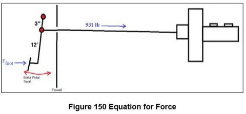

With that being said, in emergency situations, you could easily push the pedal with up to or more than 186lb of force, since most of us E30 drivers weigh more than 186lb ourselves. Not to mention, this takes into account NO SAFETY FACTOR.
Let’s try one more with the weakest – Aluminum (steel is 3x stronger than Al) – Circular Hollow (less than ½ as strong as solid square):

This means that if you push the pedal with any more than 74lb, you have a high probability of buckling your aluminum hollow circular pushrod. Of course, this does not take into account other factors such as temperature and safety factors. HIGHLY NOT RECOMMENDED.
But additional to the buckling, there’s the non-orthogonal forces creating accelerated wear on parts, causing moments to be generated on the assemblies as shown below:

The Brake Booster and the pedal linkage are not designed to be installed with only vector components (albeit major vector component) being utilized.
So in conclusion, yes, I see real risk in buckling these pushrods, unless you use a real beefy rod. Additionally, with non-linear forces and vector component forces being a big factor, I still highly suggest that you use the E34.
23.6 BRAKE PEDAL LINKAGE
E34 ASSEMBLY 23.6.1
23.6.1.1 TOOLS REQUIRED
- Various – See Figure 145
23.6.1.2 TIME & $$
- 7Hrs & $50
23.6.1.3 INSTRUCTIONS
I was fortunate enough to use the E34 Brake Linkage assembly and had to modify some parts. It is assumed that you are able to source these parts easily from the junkyard for the posted price in section 23.6.2.2.
Modification to the wheel well is one of the more difficult aspects of adapting the E34 Brake Booster Setup to the E30. I will highlight the steps necessary to help ease this somewhat daunting task. You need a welder and preferably a friend for the next few steps.
1. Grind down all other peripherals on the wheel well housing as shown in Figure 152. a. ABS mounts b. Cruise control / air filter housing tabs
2. Install engine. Have engine installed in car where its final resting place will be.
3. Position the brake booster setup in the car. It’s a tight squeeze, but it should fit.
a. This is where you might need the friend to help.
b. You must first cut Part 1. See below for instructions for cutting Part 1.
4. Align the booster where it needs to be inside the engine bay
a. Ensure that you have no interferences. Remember that the engine likes to rock sideto-side under acceleration and the closest clearance is to the oil filter assembly.
b. You must hold this position.
c. IMPORTANT: Do this step with the master cylinder installed as well. There is close clearance between the MC and the E30 Radiator Frame Rail. Figure 156.
5. Use a piece of (at least) 3/8” steel and cut to the desired shape that will fit on BOTH the Brake Booster bracket AND the wheel well housing.
a. This steel should be particularly thicker than the rest of the setup so that you can tap this steel for the mounting of the brake booster bracket.
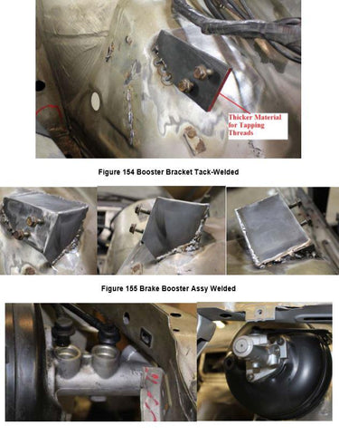
6. When you have that correct orientation, tack weld the steel to the wheel well housing. It will smoke, due to the rust prevention on the wheel well underside.
a. You might need a friend to help hold while you tack.
b. See Figure 154 Final view.
c. I recommend that this piece be substantially thicker than the rest of your brake booster setup
7. Now you can remove the engine and the brake booster setup and prepare for final weld as shown in Figure 155. The Brake Booster is final welded.
a. You must tap the screws in the proper place as shown in Figure 153. These are 13mm screws.


The E34 540i assembly is shown below in Figure 157. For those of you who do not have a donor car, this encompasses all the parts needed. I do not recommend purchasing all of these parts at retail price or it will cost a fortune. Look for someone who is parting out a BMW that fits the descriptions below and take the pedal assembly at a fraction of the price.

It is highly recommended to use the E34 Brake Linkage Assembly. This can be found on the following cars:
E32: Details on E32
- E32 740i Sedan
- E32 740iL Sedan
E34: Details on E34
- E34 530i Sedan
- E34 530i Touring
- E34 540i Sedan
Please see below for pictures of my E34 assembly and I will describe how I shortened specific parts to match:

Part 20 circled in green, while itself does not need to be modified, will need a good amount of modification on the E30 Chassis to adapt. On the E34, where the bottom of the part mounted to the chassis, does not exist on the E30 Chassis. So one will need to be created. While I realize that my pictures show some messy welds, the ideas is still there and the principles apply.
You must also drill 2 additional holes in the firewall so that part 20 can install securely on the firewall itself.

For the shortening of parts, I will herein refer to the parts as PART 1, 9, or 11.
PART 1: All you need to do for this part is cut as shown below (shorten), and drill holes for where it needs to be located. Note that Part 1 is Aluminum and the frame rails of the E30 are steel. You CANNOT weld the two together, hence my need to use the bolts. In Figure 161, you’ll see that the 2 pictures on the left are the “in construction” versions where the picture on the right is the final painted version with the linkages in final installation. I used 2 bolts/nuts to connect the E30 Frame Rail to the modified Part #1.
I do not have a dimension to cut this down to. You must use the pictures as reference


As you might be aware, these are not the only attachment points for this assembly. There are 2 attach points on the wheel well housing, which you can see below in Figure 162. This was already covered previously.

PART 9: Continuing to refer to Figure 158, you’ll see that part 9 needs to be shortened as well. This is the last part to be shortened after all other parts are in place.

This is mild steel and can simply be cut and welded together. It is mainly a bracing bar to maintain the correct distance between the two linkages. Note that you must cut the A Frame by adding this part. The A Frame can then be re-welded after you are complete with the installation. See Figure 164 for details.

PART 11: Again, referring to Figure 158, you’ll see that the linkage bar itself needs to be shortened and wewelded. This is mild steel and can easily be shortened and re-welded.
This is shown below in Figure 165. You might need to modify the E30 A-Frame as you move the brake booster linkages.

Part 11 does not have to be shortened to an exact dimension. In fact, the 2 adjusting yolks allow a lot of play for adjustment. This makes the final adjustment of the brake linkage very simple and effortless. Ensure that you screw the locknut in place when you have the linkages adjusted properly.
The final assembly of the Brake Setup, painted, polished, tested, fitted, exercised is shown below in Figure 166.

23.7 MASTER CYLINDER/BRAKE BOOSTER
Again, if you are using the Garagistic boosterless setup, there is no need to continue reading. Enjoy your simplistic and reliable setup.
I used the E34 Brake Booster that came with my 540i. All E34 540i’s and 530i’s had this remove booster setup and will have the booster and the appropriate master cylinder.
For the master cylinder, depending on what you wish to do with your existing brakes, there are a couple of options:
1. Use the E30 Master Cylinder
a. Part Number: 34311157206 - 22.2/17.4mm Master Cylinder. Meant for the E30 brakes with smaller brake calipers.
E30 Applicability
a. E30 325e Sedan
b. E30 325e Coupe
c. E30 325i Sedan
d. E30 325i Coupe
e. E30 325i Convertible
2. Use the E34 540i Master Cylinder
a. Part Number: 34311162915 – This is a 25mm Master Cylinder. Larger diameter, meaning that you will have a very stiff pedal.
E34 Applicability
a. E34 525i Sedan
b. E34 530i Sedan
c. E34 530i Touring
d. E34 540i Sedan
e. E34 525i Touring
Z3 Applicability
a. Z3 M Coupe
b. Z3 M Roadster
Some people like the feel of the 25mm master cylinder with the E30 stock brakes (or upgrades to SS lines and better pads. Many people prefer the stiffer or harder feel than softer brakes. It’s all up to your personal preferences. The takeaway here is that the E30 stock master cylinder will NOT fit on the output of the E34 540i Brake Booster. The mounting studs on the 540i booster are too big for the E30 master cylinder. In my case, I used the stock 25mm Master Cylinder, but upgraded to my E34 540i Brakes through a big brake kit offered through www.300mm.de.
23.8 ANTI-LOCK BRAKING
This is not mandatory, nor part of minimum requirements for this swap. But is recommended if a stock swap feel is desired.
PHYSICAL RELOCATION 23.8.1
The ABS pump must be relocated and there are a couple of areas to relocate. However, I decided to move it to the battery tray. This is a popular spot to relocate the ABS Pump and is conveniently located for any necessary fixes. In Figure 167, I welded the stock brackets in place. The ABS pump is mounted via 1 screw and 2 slip-stud mounts.
Note: Do not weld the brackets with the rubber bushings. The rubber will melt. Remove the rubber first and then re-glue them back in place.

See Figure 168 for the relocated ABS pump. I used 1 13mm nut to keep it in place.
For the relocation aspect of the ABS, remember a few things: 1. Make sure that all connections to the + Battery connection terminal are in-tact 2. You make provisions for brake tubing is allowed. No tight or kinked bends. 3. The wiring bundle is rather thick (3/4” diameter). Ensure that you have room!
ABS WIRING 23.8.2
The wiring of the ABS pump was NOT difficult. All you must do is detach the existing wiring from the wire bundle and relocate it to where the ABS pump currently is located. This involves splicing wires from the current location and extending them to the new location.
Remember that there are 2 red wires (12V Power) and 2 brown wires (Ground). Label each accordingly before you snip any wires.
ABS BENDING BRAKE LINES 23.8.3
Bending the brake lines is fun, but remember that each output of the ABS goes to the correct wheel. Here, you have the following inputs/outputs:
- Master Cylinder 1 Input
- Master Cylinder 2 Input
- Right Front Output
- Left Front Output
- Rear to regulator Output
Bend Brake lines with a brake line bender. NEVER USE YOUR HANDS. Kinking is a probability when you use your thumbs to bend the brakes.
23.9 BRAKE BOOSTER HOSE
23.9.1.1 TOOLS REQUIRED
- Various – See Figure 145
23.9.1.2 TIME & $$
- .1Hrs & $0
23.9.1.3 INSTRUCTIONS
The function of the brake booster hose is to assist in braking the car, making the pedal feel less stiff as it is being pushed to stop the car. This is NOT mandatory in a swap, but highly recommended to maintain a stock feel. The Brake Booster intake manifold outlet is located on the front throttle body and must be routed to the brake booster itself. You can use any vacuum hose that fits over the throttle body outlet, but you must use the check valve that comes with any E34. You can use any check valve that fits most BMW’s. See Figure 169 for details of the check valve.